ProsCut uses various techniques to cut cards accurately.
But if the layout and machine setting differ, the final cut gets shifted without cutting the card properly.
Even if we say cut shift as one word, the contents of shift are different.
The causes thereof also differ individually.

-
- Whether the knob of the paper feeding unit is locked.
- Whether the paper is curled.
- Whether crop mark lines, design print, etc., exist on the cut mark
(surrounding)
(when cut mark function used)
- Whether the surface of the paper is uneven, rough or of a specific colour.
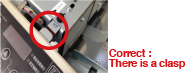
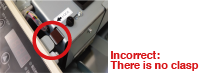
Is the paper feed unit securely clasped and locked?

The first cut is misaligned.
If the first cut is misaligned, all cards will be misaligned, all cards will be misaligned.
Open the top panel and ensure that the screws are tightened while the 2 claws of the paper feed unit are facing "LOCK" direcion.
<When the cut mark function is ON>
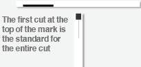
The first cut placed 3 mm below the topposition of the mark is the standard for the entire cut.
Is the cut mark funciton set correctly?
Check the settings are correct.
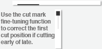
If the cut mark function is set correctly, the misalignment of vertical print position can be corrected automatically.
- When printing A4-size paper were the ■ or
 cut marks printed?
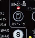
- Has the cut mark function set correctly by pressing the cut mark button on the operation panel?
Use mark ■ is The lamp blinks "with pressing the cut mark button twice.
Use mark
The lamp "lights"with pressing the cut mark button once

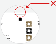
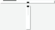
Problems may also occur if a crop mark or paint design is printed at the top of the cut mark.
 Do not put a crop mark at the top of the cut mark. When the cut mark function is ON, the cut position may be erroneously detected. The same applies to designs and stains other than crop marks.
Misalignment of vertical print position when the cut mark function no used.
<When the cut mark function is OFF (Paper edge standard)>
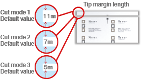
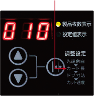
 <How to adjust tip margin dimentions>
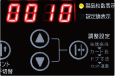
- Press the adjust settings button once
- Displays the tip margin dimensions in the currently selected cut mode. Example) For cut mode 1: displayed as 11.0 (default value)
Example) Cut mode 1: Displayed as 11.0 (default value)
- Press the △ ▽ button to set the tip margin dimesnsions ( sdjustable to ± 2.0 mm in increments of 0.1 mm)
- After entering the settings value, press the adjust settings button 4 times to return to the 4-digit unmber (productnumber display)
Note) When the cut mark function is ON, this setting value is ignored and the cut at the cut mark position becomes priority. To prioritze up margin dimenstions by manual setting turn OFF the cut mark function.

Cut position is shifted gradually
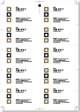
Although the first cut position on one sheet of cardboard is accurate, the shifting of cut increase as the cut progresses to the lower stage such as first stage, secound stage, third stage......
First stage

Second stage

In the first stage, the cut is accurately carried out without any shifiting.
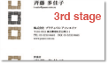
3rd stage
4th stage
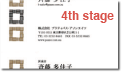
Shiftting of the cut position increases as the cut progresses to the lower stage. ( The margin between character and end of card becomes wider)
5th row
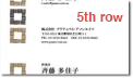
↑ If you write is manually on the A4 sheet before cutting then in the first stage and secound stage it will become easier to understand after it is cut.


Whether the setting of the cut mode is accurate?
If setting of the created layout and the selected cut mode is different, the cut position shifts gradually as the cutting progresses to the lower stage.
Cut mode display and cut mode selection button (Setting changes on pressing the button each time)
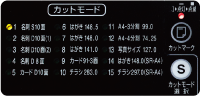
* The above photograph shows that cut mode 1 is selected.
Select the accurate cut mode according to the layout to be used.
-
Cut mode 1
(Single cut ) No Horizontal offset
-

Cut mode 3
(Double cut) Horizontal offset 3mm
-
Cut mode 2
(Duable cut ) Horizontal offset 2mm
-
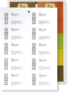
When business card design is white (single colour background) → Select mode 1 (single cut)
- When business card design is black → Select mode 3 (Double cut)
Example of dsigns to be set for mode 1 and mode 3 are here
(Note) Mode 2 (double cut) is an emergency exit mode when the business card design is missing in the non-printable area of the laser printer. Therefore, do not use this mode.

If the cut position is shifted gradually even if the cut mode is set accurately, the printing may be set to magnify/reduce or the paper may be stretched.
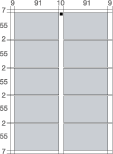
<Printing size confirmation method>
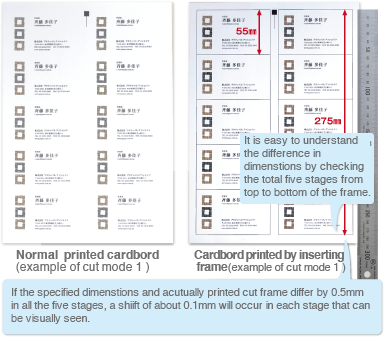
- The cut frame (ruled line) of the business card is set such that normal printing will not be carried out. Carry out setting such that the cut frame is also printed simultaneously and cutput.
- Measure the dimensions of the cut frame printed on the paper.(Measure accurately by ordinary scale, etc., of JIS standards)
- Check that the specified dimenstions of the set cut mode match with the actual dimentions of the printed cut framce.
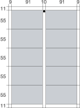
<Specified dimensons>
- Cut mode 1:
- Business card first stage length 55mm and total five stages length 275 mm
- Cut mode 2:
- Business card first stage length 55mm and total five stages. (+horizontal gap or offset) length 283mm
- Cut mode 3:
- Business card first stage length 55mm and total five sages (+horizontal gap or offset ) length 287mm
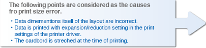
In this case, even if the cut is carried out in accurate size by the cutter,the print size is inaccurate and as a result the shift occurs in the final cut.
The cardbord on which a few errors in printing size have occurred can be corrected by adjusting the legth of the card (cut direction in paper feed direction ) to be cut using the settings of the operation panel.
The adjustable rangeis up to ± 0.5mm for the default value of the card length.
<Adjustment method for card length dimensions>
- Press Adjustment setting button twice.
- Card length dimensions (cut direction in paper feed direction) in currently selected cut mode is displayed.
Example )In case of cut mode 1: 55.0 is displayed (default value)
- Set the card length dimension by pressing △▽ button (can be adjusted in 0.1mm unit up to ± 0.5 mm)
- Upon entering the setting value, please the adjustment setting button thrice and return to 4-digit umber (display number or products)
Note) The adjustment settingvalue of the cardlength is commonly reflected to all the stages from 1 to 5 that are llaid out.
* In case of mode 2 and mode 3, the method to correct the horizontal gap or offset width is also available.

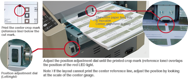
The left and right slit positions shift
Shift in print position. Not as per the specified layout.
Change the layout position or the margin setting for printing.
The left and right positions of a pre-printed paper layout with shifted margins can be finely adjusted by the left and right adjustment dials.
The adjustable range is ±3.0㎜ from the center to the left or right.
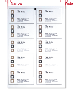
A paper layout with a cut frame to check the misalignment.
The print position is completely misaligned to left.

Gradual shift of left/right slit position.
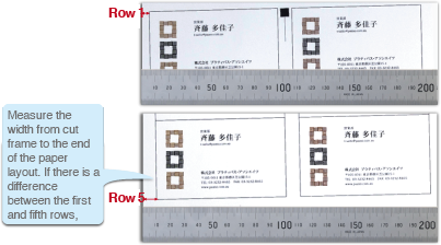
Even when the cener positions is adjusted with the left/right adjustment dial, but the left/right slit position shifts gradually as it moves from the first row →second row →third row....... and so on, the print might be oblique in the paper layout.
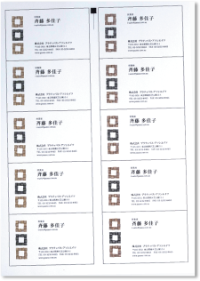
Paper layout obliquely printed
Use the same method as Conditlon 2, to cut the frame (border).
Mesure the width from cut frame to the edge of the paper layout. If there is a difference between row 1 to 5, the print on the paper layout will be oblique.
Check the printer setting ( width of paper guide, number of paper loaded, etc.)

The images on the front and back of the card are misaligned.
If the front and back images do not match in a single cut card, there will be misalignment printing back to back on A4 paper.
The product PROSCUT PCM-15W cuts based on the front of the paper.
Check printersettings, for the front and back print alignment.
To check the width of print misalignment on the front and back, print the cut frame as in Conditon 2 and measure the margins on the front and back or remove the blank sheet that has a cut marked part from the margin box using the cut mark function.

Front
Back
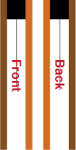
TThe front and back are not misaligned.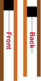
Printing on the front and back is misaligned.
Mark "front" and "back" before cutting to distintinguish front and back.


 Normal
 Misaligned
 Normal
 Misaligned
 Normal
 Misaligned

![[Normal]](../images/support/cutzure_case_01_14.png)
![[Displacement (Early cutting)]](../images/support/cutzure_case_01_15.png)
![[Displacement (late cut)]](../images/support/cutzure_case_01_16.png)